In order to improve the shifting performance, the modern automobile gearbox generally adopts a synchronizer device. In order to prevent the shifting, the combined teeth on the sliding sleeve and the gear adopt an involute tooth shape with an inverted tapered tooth. During the cutting process, cutting along the tooth direction gradually increases the tooth depth of the workpiece so that the teeth are formed into an involute tooth shape with inverted bevel teeth. In order to ensure the reduction of the tooth thickness of the workpiece, the required flank angle is formed along the tooth direction. Therefore, when inserting the tooth profile, the axis line of the shaper must be at an angle with the work axis. The value of the angle of intersection should be equal to the half angle of the root taper (hereinafter referred to as the root cone angle).
1. Determination of basic parameters of the workpiece
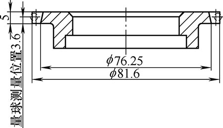
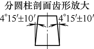
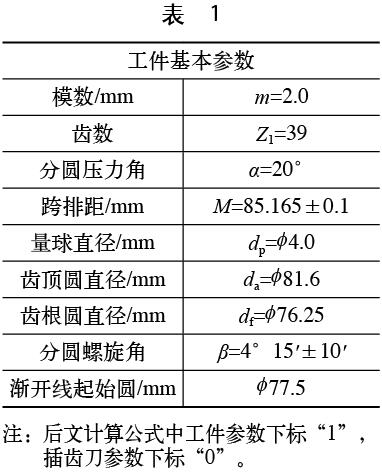
In this paper, the basic parameters of the workpiece required for designing the shaper are illustrated based on the combined teeth with a modulus of 2 mm (see Figure 1, Table 1). When the tooth profile is detected after the workpiece is machined, the gear detection center is detected based on the base circle helix angle (βb1), and the tooth radius is determined by detecting the tooth direction to determine whether the circled helix angle (β1) of the workpiece satisfies the requirement. Therefore, when providing the basic parameters of the workpiece, it is necessary to clarify the rounding or base circle helix angle of the workpiece.
figure 1
Tanβb1=tanβ1×cosα (1)
2. Calculation of root cone angle
The design of the shaper cutter can be regarded as parallel axis machining, changing the meshing center distance of each section to obtain the theoretically required rounding helix angle and root taper angle.
(1) Calculate the parameters of the gear shaping cutter by taking any cross section of the workpiece (based on the big end as an example) as the design basis.
Large end tooth thickness  

(2)
Small end tooth thickness

(3)
Engagement angle

(4)
Mesh center distance
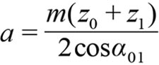 (5)
(5) Insert tooth top circle

(6)
Where x1 is the displacement coefficient of the large end of the workpiece tooth thickness; B1 is the distance of the measuring section from the large end; B is the effective tooth surface width of the workpiece; S1 is the measuring section tooth thickness (calculated according to the span distance); df1 is the workpiece large End tooth root diameter.
From the above formula, the outer diameter da0 of the new shaper blade can be calculated.
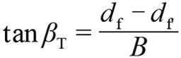
(2) Determine the actual root cone angle. Calculate the small-end displacement coefficient x1 of the workpiece from equations (2) and (3), and calculate the root diameter df of the small end of the workpiece according to the outer diameter of the shaper and formulas (4), (5), and (6). .
The above calculation can be used to obtain the actual root cone angle βT of the workpiece.
.
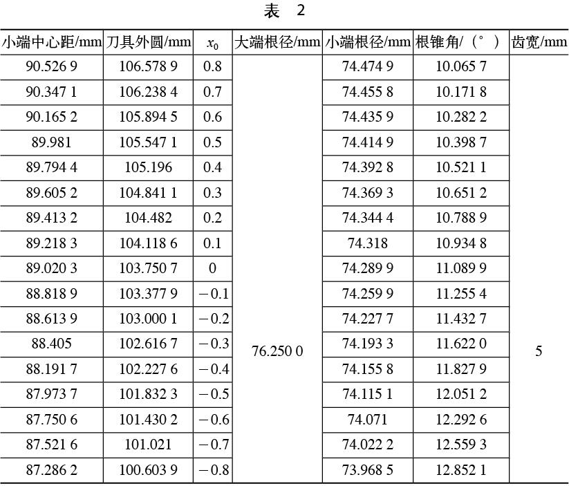
It can be seen from the above results that as the tool is continuously repaired, the displacement coefficient of the tool is gradually reduced, and the actual root taper angle of the workpiece is not a fixed value, but a certain curve change (see Table 2). The number of teeth of the pinion cutter is z0=50, and the result is calculated.
3. Tool optimization design to improve tool life
According to Table 1, it can be seen that in the actual machining, as the tool is ground and the displacement coefficient changes, to obtain the theoretically correct rounding helix angle, the root cone angle must be changed, but in the actual processing, the root The taper angle (the degree of movement of the machine tool) is generally fixed, which in turn causes a change in the helix angle of the workpiece during machining. Therefore, this paper focuses on the rationalization of the new tool displacement coefficient, and guarantees the maximum amount of tool sharpening (effective service life) within the allowable range of angular error of the split helix angle.
When designing the tool, select a certain displacement coefficient. According to Table 1, the corresponding fixed root cone angle can be determined. According to the above formulas, the actual tooth thickness of the small end of the workpiece can be inversely calculated. The actual circular spiral can be calculated by formula (3). The angle β, according to the requirements of the workpiece parameters, ensures that the difference between the actual and the theoretical rounding helix angle is within the tolerance requirements:

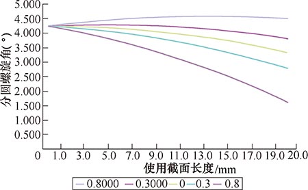
Figure 2 shows the change trend of the actual rounding helix angle with the new tool when taking different displacement coefficients.
figure 2
In Table 2, the new tool displacement coefficients of 0.8, 0.3, 0, -0.3, and -0.8 are calculated separately. According to the data analysis, when the new pinion cutter displacement coefficient is 0.3, the fixed transfer angle is The effective length of the knife is approximately 13 mm. Starting from the statistical analysis of data, in the design of this type of pinion cutter, the design of the new pinion cutter is further optimized according to the limitation of the design of the normal pinion cutter.
4. Conclusion
In this paper, the basic parameters of the workpiece required for the tool design are introduced in detail, and the concept and transformation relationship of the helix angle and the base circle helix angle of the workpiece are clarified, and the parameter analysis of the ambiguity is avoided to cause the tool. The wrong design affects the processing cycle; the machine tool rotation angle during machining is calculated in detail, and the machining and repeated detection of the sample during machining are reduced to adjust the movement of the machine tool; from the theoretical requirements, through the optimization design of the tool, Accurately calculate and guarantee the theoretical service life of the tool; according to the above data analysis, with the sharpening of the pinion cutter, the machine tool movement in the actual machining cannot be changed, resulting in the tool processing size being too poor. Therefore, the use of such tools The life cannot be equal to the normal shape cutter. The selection of the new tool displacement coefficient directly affects the life of the tool.
references:
[1] Yuan Zhejun. Gear Tool Design [M]. Beijing: National Defence Industry Press, 2014.
[2] Yuan Zhejun, Liu Huaming, Tang Yisheng. Gear Tool Design [M]. Beijing: New Era Press, 1983.
As a China leading manufacturer and suppliers of TFT-LCD panels,we are specialized in many brands TFT-LCD,Touch Screen,Touch Screen Display from 2 inch to 65 inch for Industrial,Medical,Marine,Amusement,Home Automation,Avionics,Consumer application.
The Thin film liquid Crystal Display, commonly referred to as the TFT-LCD, is a type of liquid crystal display that USES thin-film transistor technology to improve the image quality. Although TFT-LCD is collectively known as LCD, it is an active matrix LCD used in televisions, flat screens and projectors.
In a nutshell, TFT - Lcd Panel can be seen as two pieces of glass with a layer of liquid crystal, middle of the upper glass substrate is a color filter, and it has lower level of glass on the transistor set in. When the current passes through the transistor, the electric field changes and the liquid crystal molecules deflect, so as to change the polarization of the light, and then the polarizer is used to determine the light and dark state of the pixel. In addition, the upper glass is fitted to the color filter, so that each pixel contains three colors of red, blue and green, which make up the video image on the panel.
Touch screen (Touch Panel) is also known as "Touch screen", "Touch Panel, Touch is a kind of can receive the first input signal of induction type liquid crystal display device, when contact with the graphic buttons on the screen, the screen of the tactile feedback system according to the program of pre-programmed drive all kinds of connecting device, can be used to replace the mechanical button Panel, and liquid crystal display screen by creating vivid audio effect.
As a kind of latest computer input device, touch screen is a simple, convenient and natural way of man-machine interaction. It endows multimedia with a new look and is an attractive new multimedia interactive device. It is mainly used in public information inquiry, industrial control, military command, electronic game, multimedia teaching and so on.
TFT-LCD Panel
Tft Panel,Tft Touch Screen,Tft Lcd Touch Screen,Tft Touch Screen Display
Tonya Display Limited , https://www.tydisplay.com