[ Huaqiang Security Network News ] 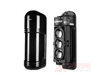
Detailed explanation of the installation method of infrared radiation
First, the installation of the infrared detector is more difficult than the passive infrared detector, but it is only slightly complicated. However, as long as you have a good understanding of the wiring method, location determination, debugging, and carefully follow the instructions, I believe there will be no problem.
The infrared radiation detector is mainly composed of a protective cover, a mounting seat, a tamper switch, an infrared light transmissive sheet, a circuit board, a boundary line seat, an adjustment switch, an outer casing, etc., and is not complicated as imagined. Before installation, it is best to use a pencil or other tools to achieve the location of the installation according to the design (or to place the infrared detector on the installation site), and then use the level or other tools to determine the installation location, to ensure that The accuracy and aesthetics of the installation.
How to install the infrared detector
1 Pillar installation: The more popular pillars are round and square. The early popular ones are circular section pillars. Now the situation is just the opposite. Square pillars are becoming more and more popular in the engineering world. Mainly the detector is mounted on the square pillar without rotation and is not easy to move. In addition, a wide range of stainless steel, alloy, aluminum alloy profiles are also one of its advantages. Another method in the work is to use angle steel as the pillar. If it is not guaranteed that the route is effectively worn through the pipe and the line is exposed in the air, this method is not acceptable.
The shape of the pillars can be "1" shape, "z" shape or curved, depending on the characteristics of the building and the anti-theft requirements. The key point is that the fixing of the pillars must be firm and firm, without displacement or shaking, to facilitate installation and Fortification and reduce false positives. ;
2 Wall-mounting: Now the manufacturer of active infrared detectors at the forefront of the anti-theft market can provide infrared detectors with a horizontal angle of 180° and a tilt angle of more than 20°, such as aleph active infrared detectors ha, abt, Abf series products can support the probe to be installed directly on the outer wall of the building or on the fence and fence.
General principles for the installation of infrared detectors
The detectors installed on the channel are mainly functional and prevent people from illegally passing. In order to prevent false alarms caused by pets, small animals, etc., the position of the probe should generally be more than 50 m from the ground. The shading time should be adjusted to a faster position to respond quickly to illegal intrusions.
The main function of the detector set on the wall is to prevent man-made malicious over-the-counter, both top and side mount.
The detector mounted on the top should be positioned higher than the fence and 25 m at the top of the wall to reduce false alarms caused by birds and kittens moving on the wall. The four-beam detector has stronger anti-false alarm capability than the dual beam, and the dual beam is stronger than the single beam.
The side installation is to install the probe on the fence, the wall is close to the top side of the wall, generally for wall installation, mostly installed on the outside. This way can avoid the interference of birds and kittens.
Each method has its own advantages or disadvantages, and the engineering firm has their own preference for each installation. Users should choose according to the characteristics of their buildings and anti-theft requirements.
Special reminder for infrared radiation installation
1. The line must not be applied clearly, and it must be hidden by the tube. This is the minimum requirement for the safety of the detector.
2. The detector mounted on the wall shall have a maximum horizontal distance of no more than 30 m from the wall, which requires special attention when the wall is curved in a curved shape.
3. After the wiring is connected, test the power supply terminals 1 and 2 of the probe with the resistance of the multimeter to confirm that there is no short-circuit fault before turning on the power for debugging.
Infrared radiation connection method
The power supply is connected in positive and negative polarity. You can treat all the wired detector alarm output parts as one switch. Generally, there are 3 terminal blocks com (common) / nc (normally closed) / no (normally open), we often The com and nc are used, and the alarm alarm input terminal of the alarm host is connected. If the alarm host has a tamper-proof tail resistance, the tail resistance must be connected to the detector, not to the end of the host, otherwise the anti-vandal function will be lost.
The resistance of the wired alarm host is called the "wire tail resistance". As the name suggests, it should be connected to the end of the line, that is, the detector. Anti-destruction function, short circuit, open circuit will alarm. Do not connect directly to the host, otherwise, the manufacturer is not as good as soldering on the circuit board. Many beginners make similar mistakes. I hope to draw attention.
Engineering debugging of infrared detector
(1) Optical axis adjustment of the emitter
Open the cover of the probe, aim the eye at the sight, and observe the influence inside the sight. The optical lens of the probe can be adjusted directly by hand in the range of 180°. Use a screwdriver to adjust the upper and lower adjustment screws under the lens. The lens system has up and down. The adjustment range of 12° is repeatedly adjusted so that the influence of the opposing detector in the sight falls into the center position.
Be careful not to cover the optical axis during the adjustment process, so as not to affect the adjustment work.
The adjustment of the optical axis of the emitter has a great influence on the sensitivity performance of the zone. Please be sure to repeat the adjustment according to the correct steps.
(2) Optical axis adjustment of the receiver
Step 1: Perform a preliminary adjustment of the optical axis of the receiver in the same way as the "lighter adjustment of the optical axis". At this time, the red warning light on the receiver is off, the green indicator light is on, and there is no flicker, indicating that the optical axis of the ferrule is coincident, and the emitter and receiver are functioning normally.
Step 2: There are two small holes on the receiver, which are marked with "+" and "-" respectively to test the intensity of the infrared light perceived by the receiver. The value is expressed by voltage, which is called the light voltage. Insert the test chart (red "+", black "-") of the multimeter into the light-receiving voltage of the measuring receiver. Adjust the lens system repeatedly to maximize the value of the light. In this way, the working state of the probe is at its best.
Note: The four-beam detector has two sets of optical systems. It is necessary to cover the upper and lower lenses of the receiver separately and adjust until the upper and lower photosensitive voltage values ​​are the same. The two sets of optical systems of the older four-beam detectors are separately adjusted. Because of the corresponding relationship between the four optical systems of the transmitter and the receiver, it is difficult to adjust and needs to be adjusted carefully. If it is not handled properly, it will be handled improperly. There is a false alarm or a dead zone. The abf four-beam detector has integrated the two parts into one unit, making engineering construction much easier.
(three) shading time adjustment
The light-receiving time adjustment knob is provided on the light receiver. Generally, the light-shielding time of the probe is adjustable from 50m/s to 500m/s. When the probe is shipped from the factory, the shading time of the probe is adjusted to a standard position in the factory. Next, this position is a relatively moderate state, taking into account the environmental conditions and the characteristics of the probe itself, so there is no special reason, and there is no need to adjust the shading time. If it is necessary to adjust the shading time due to the fortification, to adapt to changes in the environment. In general, the shading time is short, the sensitivity of the probe is fast, but the sensitivity to falling leaves, flying birds, etc. is also strong, and the possibility of false alarms increases. The shading time is long, the sensitivity of the probe is reduced, and the possibility of underreporting is increased. The engineer should adjust the shading time according to the actual needs of the fortification.
Infrared detector connection to the alarm host
After the probe is set, connect the tamper switch to the input circuit of the zone. After the wire is connected, cover the outer casing of the probe and tighten the fastening screw. It is required that the zone warning light on the anti-theft host is not flickering or lighting, and there is no alarm indication output in the zone. Indicates that the entire zone is set properly. Otherwise, check the line, re-commission the probe, and re-determine the status of the zone.
Infrared radiation detector performance test
After the working condition of the zone is normal, the optical axis of the probe should be blocked by different speeds and different ways according to the requirements of the fortification, and all the possible sizes and shapes similar to the precautions should be used to contact the control center with the wireless walkie-talkie at the alarm site. Check if the alarm condition is normal, and be careful to check if there is any flashing or unstable state on the alarm host. So as not to leave hidden dangers to the alarm system. We verbally call this process a gun test. The purpose of the gun test is to test whether the zone has the ability to have a normal alarm, whether the scope of the zone protection can meet the predetermined requirements, and whether there is a protective dead zone.
Routine maintenance of infrared detectors
In the daily work, the detector is inevitably exposed to dust, microorganisms, snow, frost and fog in the atmosphere. For a long time, a layer of dust-like hard is often accumulated on the outer wall of the detector. The shell, in a relatively humid place, will also grow a thick layer of canola, and sometimes the bird will also pull the waste to the detector, these things will hinder the emission and acceptance of infrared radiation, causing false alarms. Therefore, it is necessary to carry out maintenance at regular intervals. Usually, clean the outer casing of each detector with a cleaning agent for about one month, and then dry it. In addition to cleaning the detector housing, a firing experiment is performed every other month to verify the alarm performance of the anti-theft system.
Aluminium Plate,Aluminum Stucco Embossed Plate,Aluminum Chequered Plate
Henan Everwin Trade Co., Ltd. , https://www.ewaluminium.com