Abstract Optimized tool design has a key role Carbon fiber reinforced composite (CFRP) has a wide range of strength and weight ratios and stable material properties under extreme conditions, so it has a wide range of applications in the global aerospace industry. This material can...
Optimized tool design has a key role
Carbon fiber reinforced composites (CFRP) have a wide range of applications in the aerospace industry worldwide due to their high strength-to-weight ratio and stable material properties under extreme conditions. This material can be used alone or in combination with titanium and aluminum. For example, 80% of the Boeing 787 Dreamliner is made of composite material, equivalent to 50% of its weight, which can reduce the use of 1,500 sheets of aluminum and 50,000 fixtures. Compared with Boeing 767, it can save 20% fuel consumption. At present, there are still many problems in the joining technology such as gluing and welding; therefore, the riveting and fixing technology still occupies a mainstream position in practical applications. Because of the great difference in mechanical properties between carbon fiber materials and metal materials, it is necessary to use cutting tool products with high wear resistance and optimized groove shape for effective drilling of the fastening holes.
When processing spare parts in the aerospace industry, polycrystalline diamond (PCD) tools have higher processing efficiencies than conventional tungsten carbide carbide knives. Some leading tool manufacturers are developing and producing PCD brazed drill products. The cutting edges of these tool products are made of PCD material, and the body part is made of solid carbide. The carbide drill body has good rigidity and dimensional accuracy, ensuring the quality of the drilling, and has an internal spiral cooling channel. The spiral flute can improve the cooling performance and chip removal performance. These characteristics are very important for drilling. necessary. The cutting edge part of the functional area is made of PCD material, which has excellent wear resistance and improves processing efficiency.
Optimized tool design plays a key role in ensuring excellent drilling quality when machining advanced aerospace composites. In the tool size design, many necessary factors have a significant impact on the quality of the drill hole. For example, in order to reduce the cutting force, the sharpness of the tool nose radius is increased, and the rake angle is increased. Other factors include reducing the tip angle to reduce propulsion and avoiding tearing of the fiber material, and optimizing the edge design to improve burr height control performance. The rigidity of the machine tool, the spindle and the overall tool, the tool holder, the internal cooling or jet cooling, and the material of the drilled workpiece are also important factors to consider during the tool design process. In most cases, in order to meet the different needs of customers, it is necessary to provide customers with customized tool products in a timely manner.
Tool development process
In order to develop a high-performance PCD tool product, in-depth research should be conducted taking into account the combined factors. This development process not only determines the performance of the tool, but also plays an important role in the processing efficiency and cost of the tool.
There are four main techniques that can be applied when producing synthetic diamond drill bits for composite processing:
- CVD (Chemical Vapor Deposition) Diamond Coated Drill
The solid carbide drill is processed in the final process by a CVD diamond coating. This is a cost-effective product, but the sharpness of the edge is affected by the thickness of the coating. In addition, because of the different hardness of the cemented carbide base portion and the diamond coated portion, this product does not absorb impact energy. Anti-cracking performance is also limited.
- PCD insert bit
The conical PCD material is sintered to a smaller size cemented carbide substrate according to the characteristics of the drill tip groove. These semi-finished products are then brazed onto the solid carbide drill body. To handle the high stress problems between cemented carbide and PCD joints, this PCD product is limited in PCD material optimization. The post-sintering process can also be costly because of the need to remove the diamond material in the non-functional zone and the internal cooling holes.
- PCD weft drill
The PCD powder raw material is filled in a pre-processed tank above the solid carbide bar, and then subjected to high temperature and high pressure treatment to form a PCD array structure. After the high temperature and high pressure process, the bar material is sheared and brazed onto the drill body, and finally the grinding process is carried out according to the specified groove type. This PCD embossing technology can produce complex geometries as well as tooling products with a high positive rake angle; less grinding is required compared to PCD insert tool products. This type of tool is limited in size because of the high temperature and high pressure processing of complex 3D geometry. In addition, the hardness and wear resistance of PCD materials are also reduced because materials that require high cobalt content are often required.
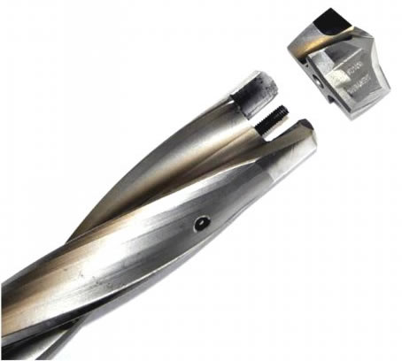
- PCD brazing drill bit
The most mature PCD bit machining technology is 2D technology (eg PCD flat drill). For smaller size tools, a special carbide and PCD sandwich material can be used; for larger size tools, pure PCD drill tip material can be used. This product has serious drawbacks in terms of geometry because it is difficult to add a front corner for composite processing. 3D brazing requires multiple PCD holders of the required material and the microstructure should be cut into a spiral shape as designed. A corresponding spiral groove should be ground on the solid carbide drill bit to mount the PCD insert. Compared to PCD inserts, this 3D brazing product uses PCD material only in the functional area, which greatly increases the processing performance. This 3D brazing technique was used to develop the PCD test bit described herein.
Another important factor in choosing a PCD material is the machinability of the diamond material. Machinability is assessed by calculating the time to make the same tool from different PCD raw materials. Focus on individual manufacturing steps, including corrosion of PCD cutterheads and grinding of PCD materials. Refer to the measurement levels in Table 1 for the results of the machining performance test. The better the machinability, the higher the grade, the shorter the manufacturing time and the lower the cost; this is the same as the tool performance when developing a competitive tool product.
PCD brazing
The tooling products described in this paper require the PCD spiral section to be brazed to a tungsten carbide body. The brazing technique used should avoid graphitization of the metastable polycrystalline diamond and the bonding of PCD to tungsten carbide. This requires efficient brazing techniques. Efficient brazing materials typically include high melting point polymeric materials such as titanium materials. The brazing temperature is therefore high and has a negative effect on the stability of the diamond phase. In order to avoid graphitization, an oxidizing environment should be avoided during the brazing process. The latest technologies include induction brazing in argon environments and vacuum brazing.
Optimized tool geometry
When drilling composite/titanium laminates, it is very difficult to select an optimized tool geometry because the two materials exhibit different characteristics during the cutting process. Drilling of CFRP materials typically requires large helix angles and long cutting edges because the carbon fibers should shear along the cutting edge. The long cutting edge is achieved by a small drill tip. In addition, the drilling of CFRP materials should also reduce axial forces to avoid cracking of the machined material during retraction. These features result in a very sharp cutting edge geometry while also reducing the wedge angle. The back angle can be as high as 20 degrees and the helix angle is about 30 degrees. Titanium cutting can in principle also use sharp cutting edges, but requires a more stable wedge angle than drilling of CFRP materials. The tool relief angle in titanium machining is typically in the range of 8-14 degrees. These relief angles are typically larger (about 12 degrees in the product shown here) as compared to steel material processing because the heat on the flank should be as low as possible to reduce the wear on the side of the knives. When the large relief angle is combined with a typical 30 degree helix angle, the strength of the cutting edge is significantly reduced. The helix angle has been reduced to a range of 15-20 degrees so that the large relief angle can be balanced. The manufacturing process presented in this paper can select different helix angles depending on the desired tool geometry. This is one of the main advantages of the process presented in this article, as the average PCD tip-edge insert allows a maximum helix angle of only 8 degrees.
In order to achieve tight bore tolerances, it is absolutely essential that the drill tip should have excellent self-centering performance. From another perspective, the tip angle also plays an important role in the formation of burrs. We know that a tip angle of less than 90 degrees or more than 150 degrees can help reduce the burr height at the exit of the hole. Therefore, a drill with a drill angle of 155 degrees is suitable for the processing of titanium materials, but the centering performance is not good. Therefore, it is recommended to use a double-drilled corner design with an internal drill angle of 130 degrees and an external drill angle of 155 degrees. This drill has a lower overall drill tip height compared to conventional long edge cutting bits. Therefore, the third and fourth land strips can quickly contact the material, which is beneficial for forming tighter aperture tolerances.
Custom modular drill bit with PCD brazing insert
Another advantage of this displayed bit product is its internal cooling performance. When drilling pure CFRP sheets, the inner cooling holes promote the rapid discharge of CFRP chips through the drill flutes under the action of compressed air. When processing CFRP/titanium laminate material, it can be lubricated through the sealed internal cooling passage (MQL), which can promote the lubrication and reduce the high heat formed in the processing of titanium material because of the thermal conductivity of this material. Lower. Minimal lubrication is absolutely necessary when drilling with PCD tools; otherwise, the high heat generated at the cutting edge can lead to graphitization or the formation of titanium carbide. This reaction can cause chemical wear in the flutes and eventually cause the PCD material in the flutes to crack.
Experimental research
This developed PCD tool product has been experimentally tested to evaluate the most suitable PCD material and tool geometry for the specified application. The tool settings and cutting parameters during the test are as follows.
- Test tool
PCD brazed drill bit, 11.113 mm (7/16 in.) in diameter, three different PCD materials (G4, KD1415, and KD1425), uncoated with the same groove type drill.
- Test materials
The test material consisted of a 8.7 mm (0.342 in.) purchased CFRP sheet (Isocarbon 3k) and was firmly laminated to a 10.6 mm (0.425 in.) Ti-6Al-4V sheet. Through-hole machining using a test tool, feeding from the CFRP side, and cutting from the titanium plate side
- Machine tools and coolants
One CNC machining center (Heckert CWK 400), horizontal spindle, and spindle-through micro-lubrication (Vascomill MMS FA2).
- Cutting parameters
The cutting speed is 20 m/min (65 SFM) and the feed rate is 0.05 mm/rev (0.002 ipr). It is also suitable for CFRP and titanium material processing. Do not use the boring method.
- Tool detection
In order to monitor the tool wear process, the drill bit is inspected using a microscope after drilling 4 holes. After completing the drilling of 24 holes, the wear structure of the tool was observed under a scanning electron microscope.
- Drilling measurement
After all processing tests have been completed, the test materials are cleaned and labeled. All drill holes are tested. Diameter measurements were taken on the inside of the 4 holes (two at the inlet and outlet of the CFRP plate and two at the same position on the titanium plate). At the same time, the burr height of the surface of the exit hole at the bottom of the titanium plate was measured.
Results and analysis
Extremely long, predictable, and stable service life are the main factors that determine whether a tool product can win customers. When drilling CFRP/Ti composite matrix materials, in order to obtain satisfactory drilling quality, several requirements must be met at the same time. The diameter of the drill hole is tight tolerance to install the fastener, and the height of the burr at the exit of the drill must meet the specified requirements to reduce or avoid the deburring process. In order to avoid damage to the borehole caused by a sudden change in the tool and to maintain the wearability of the tool, the chipping of the drill tip must be minimized and monitored. The following criteria are used to determine if the test tool has reached the end of its life:
a) The borehole dimensional tolerance is 11.113 + 70 microns (H10);
b) the burr size is 0.2 mm;
c) the tip of the drill is chipped
Tests have shown that the main failure mode of the PCD bit at the end of its useful life is the chipping of the drill tip;
The failure mode of cemented carbide drills is characterized by a burr height overrun. In this test, all drill holes met the drilling quality requirements.
Drilling size
Figure 1 shows the dimensions of the drilling process for testing PCD tools. When measuring each hole, the measurement position of the aperture is selected at 4 different positions; 2 in the CFRP plate and 2 in the titanium plate; corresponding to the inlet and outlet surfaces of the hole.
Figure 1: Comparison of the number of drilled holes and the size of a PCD tool
It can be seen that the quality of the drilled hole in the titanium plate is very good, the size is in the middle of the specified tolerance value, and the upper and lower floating range is very small, 10 microns. The dimensions of the titanium plate drilling entrance and exit are very close. However, in the CFRP sheet, the difference in the diameter between the entrance and exit of the borehole is large. This phenomenon is caused by the fact that the chips avoid scratching the hole during the chip removal process. Increasing chip control performance is necessary to reduce chip scraping and increase the consistency of the hole size. It is very difficult to improve the chip control performance by simply relying on the tool design. In processing practice, a mature process is to increase the boring operation or to support the drilling operation by vibration to control the chip length and reduce the chip scraping effect.
Test results show that the new drill tip products shown here can be drilled to the H10 tolerance class. The drilling size of the H8 tolerance class can even be achieved with optimized machining conditions and stable machining processes. It cannot be proved that the quality of the drill is intrinsically related to the material of the cutting edge. The drilling quality of PCD drill bits and carbide drill bits of the same drill tip type is similar.
glitch
When exploring the results of drilling associated with burr height control and wear structure, the different results produced by different cutting edge materials can be clearly seen. Figure 2 shows the comparison of the development of the burr height with the number of holes in a carbide tool and two PCD (KD1415 and G4) tools.
Figure 2: Comparison of the development process of burr height and the number of boreholes due to tool wear
It can be seen that the burr height at the exit of the titanium plate is significantly increased after the cemented carbide drill has only completed 14 drilling operations; and the first burrs of the two PCD tools during the machining process exceed the specified drilling holes. 57 holes and 117 holes.
In theory, the development of the burr height is closely related to the wear of the tool tip. This can be seen in the comparison of cemented carbide tools and PCD tools because the hardness of the two materials is very different; therefore, the wear development at the PCD tool tip is slower. Compared to carbide drills, PCD drills have much less wear on the drill tip. The wear development of these three PCD materials is very different. The main wear type of PCD material is the chipping of the cutting edge/drill tip.
The table provides a comprehensive comparison of the tool life of these three PCD test materials. It can be seen that the G4 and KD1415 materials are very similar in terms of tool life. The KD1415 performs better in terms of tool life stability and reduces manufacturing costs due to better machining performance. Therefore, it is selected as the most suitable material in the processing applications described herein.
in conclusion
We have developed and tested these three PCD solid carbide brazed drill bits with different PCD materials and optimized geometries. The test conclusions are as follows:
1) In the PCD tool manufacturing process, 3D brazing technology allows the tool to have a flexible helix angle, so a large rake angle design can also be used. Compared to PCD inserts, 3D brazing products have better machinability because they remove PCD material from the surface of the tool's functional area;
2) This developed PCD drill product uses an optimized tool geometry (double drill tip angle, spiral groove, internal spiral cooling channel, large rake angle), so it can process high quality drilling (drilling diameter and burr height) control).
3) PCD drills have a significant improvement in service life compared to uncoated monolithic carbide drills.
4) All tested PCD knives have the same wear pattern, starting with fine cracks in the rake face and eventually causing abrupt failure due to chipping of the drill tip.
5) The KD1415 performs better than the G4 and KD1425 materials in terms of tool life stability and machinability. Therefore, the KD1415 is the material most suitable for the processing applications described in this article.
As a leader in the industry, Kennametal celebrates its 75th anniversary, providing innovative product solutions to customers seeking the best product performance under demanding processing conditions to help customers increase productivity. Kennametal Technologies uses state-of-the-art materials technology to provide innovative wear-resistant products, products and application designs to customers in aerospace, road and mining, energy, and industrial production in 60 countries. Application technology services. The company employs approximately 14,000 people and has sales totaling nearly $3 billion; half of the company's operating income comes from markets outside of North America; total sales of new products over the past five years accounted for 40% of global sales. Kennametal focuses on safety and has earned the title of "World's Most Ethical Business" (Moral Village Association), "Outstanding Innovative Enterprise" (Product Development Management Association), and "The Safest American Enterprise" (EHS Today Magazine) ); Kennametal and its foundations continue to invest in areas such as technology education, industrial technology, and materials science, demonstrating the fascinating prospects of industry development and economic prosperity. (For more information, please visit the company website: Â )
100 Waterproof Flooring,7Mm Spc Flooring With Ixpe,Easy Install Spc Flooring,Rigid Spc Flooring
Jinan Caiming Wood Co.,LTD , https://www.caimingflooring.com