Installation Methods for Cylindrical Bore Bearings
When installing or removing cylindrical bore bearings, it's essential to consider the bearing's layout, size, and the type of fit between its components. The installation force should be applied directly to the end face of the inner ring that is tightly fitted, avoiding any transmission of pressure through the rolling elements. This is crucial because applying force through the balls or rollers can cause indentations on the raceway, leading to improper operation or even damage to the bearing. Bearings often have delicate parts such as the cage, seal rings, and dust covers. These components are prone to deformation, so it's important not to apply direct pressure to them during installation or removal. Instead, use appropriate tools and techniques to ensure a smooth process. ### 1. Inner Ring Tight Fit with Shaft, Outer Ring Loose Fit with Housing If the inner ring is tightly fitted to the shaft and the outer ring is loosely fitted to the housing, you can first press the bearing onto the shaft using a press. Then, insert the shaft into the housing along with the bearing. A soft metal sleeve (such as copper or soft steel) should be used on the end of the bearing. The inner diameter of the sleeve should be slightly larger than the journal diameter, while the outer diameter should be smaller than the inner diameter of the bearing's rim. Adding a handle to the sleeve can make the process easier. Ensure the bearing is aligned properly with the shaft to avoid tilting, which may cause indentations, scoring, or even cracking of the inner ring. In cases where a press is unavailable, a bearing sleeve and small hammer can be used, ensuring even pressure is applied around the entire end face of the bearing ring. The hammered surface should be rounded to prevent uneven force distribution. ### 2. Outer Ring Tight Fit with Housing, Inner Ring Loose Fit with Shaft In this case, the bearing can be pressed into the housing first. The outer diameter of the installation sleeve should be slightly smaller than the housing bore. This ensures proper seating without damaging the bearing. ### 3. Both Inner and Outer Rings in Tight Fit When both the inner and outer rings are tightly fitted, the installation sleeve should be designed to press the end face of the inner ring. Alternatively, a disc and sleeve combination can be used to apply even pressure to both rings simultaneously. This method is particularly suitable for spherical bearings that require self-centering during installation. ### 4. Heating Method for Large Bearings For medium and large bearings with significant interference fits, the heating method is commonly used. The bearing or the component to be installed is heated evenly to 80–100°C in an oil bath or special heater (not exceeding 100°C). Once removed from the heater, the bearing should be wiped clean with a non-cotton cloth to remove any oils or residues. It is then carefully placed over the mating part and pushed into position in one smooth motion. During cooling, it’s important to maintain tightness or gently tap the bearing with a small hammer through the installation sleeve to ensure proper alignment. If the outer ring is tightly fitted to the housing, the housing itself can be heated before being inserted into the bearing. ### 5. Special Considerations Bearings made of light metal materials may be more susceptible to damage during installation. In such cases, heating the bearing housing is recommended to reduce the risk of damage. Always ensure that the bearing is rotated slightly during installation to prevent misalignment or sticking. --- **Related Articles:** - What issues should be considered when selecting crankshaft bearings for Xiali engines? - Common misconceptions about using bearing steel in special environments and replacing roller bearings - Understanding the correct application of bearing steel tumble bearings This article was originally published on China Bearing Network. For more information, visit [http://www.chinabearing.com](http://www.chinabearing.com). Previous: NTN Bearing Oscillation Elements Next: Abnormal Sounds After Transmission Gear Engagement
Insulator Hardware
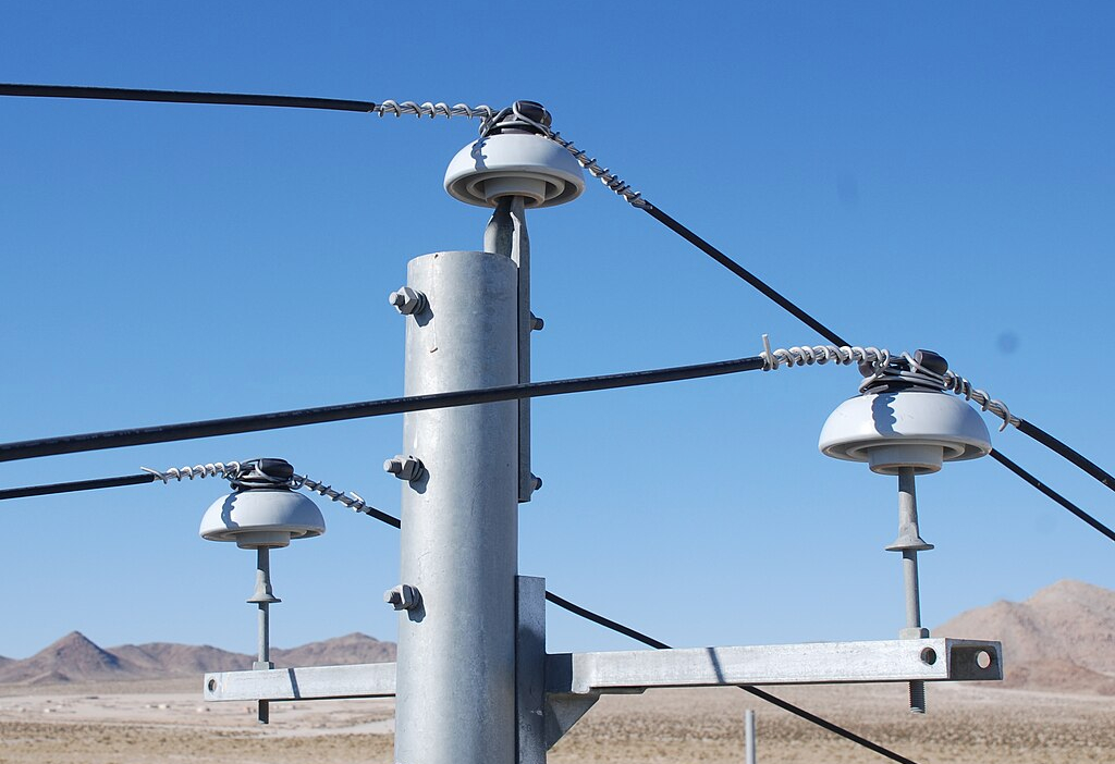
Insulator hardware for Poleline Hardware refers to the components used to support and insulate electrical conductors on utility poles. Some common insulator hardware used in poleline installations include: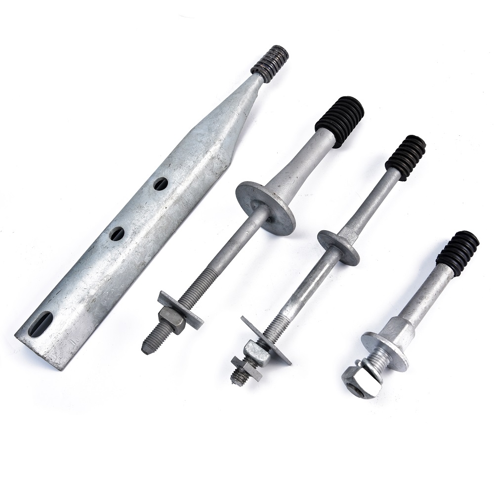
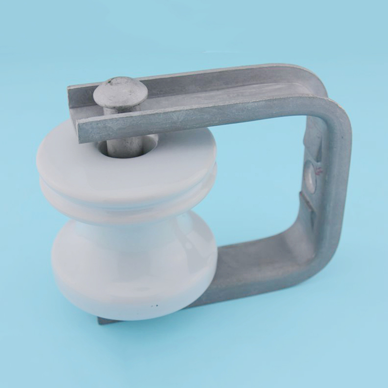
1. Insulators: Insulators are typically made of porcelain, glass, or polymer materials and are used to prevent electrical current from flowing through the pole or other grounded structures. They provide electrical insulation and mechanical support for the conductors.
2. Insulator pins: Insulator pins are used to secure the insulators to the crossarms or other supporting structures. They are usually made of steel or other durable materials and come in various designs to accommodate different types of insulators.
3. Insulator Clevis: Insulator clevis are comprised of multiple insulators connected in series to provide the required electrical insulation for the voltage carried by the conductors. The number and arrangement of insulators in a string depend on the system voltage and other factors.
4. Suspension hardware: Suspension hardware includes various components such as suspension clamps, suspension insulators, and suspension links. These are used to support the weight of the conductors and insulators, ensuring proper tension and alignment.
5. Strain hardware: Strain hardware is used to absorb and distribute the mechanical forces exerted on the conductors due to wind, ice, or other external factors. It includes components such as strain insulators, strain clamps, and dead-end fittings.
6. Crossarm braces: Crossarm braces are used to provide additional support and stability to the crossarms, which hold the insulator strings. They are typically made of steel or other sturdy materials and help to prevent sagging or swaying of the conductors.
Yokelink Insulator Hardware are mainly used in transmission lines. It is used to connect crossarms, thereby joining the crossarms. By joining crossarms together, they are made stronger and more resistant to vibration.They are attached in cross arms of overhead transmission lines for supporting and connecting the crossarms by means other than welding. They join two crossarms or a cross arm with an insulator mounted on it. It is also put into one crossarm for joining cross arms together.
The Insulator cross arm pins have three parts – the crossarm pin base, a crossarm pin body, and the crossarm pinhead. The cross-arm pin base is fitted in an opening of a cross arm.The cross-arm pin body connects the cross arm with another cross arm or a crossarm insulator. The crossarm pinhead is placed on the top end of the cross-arm pin body and holds it into position so that it cannot move outwards.
Insulator Clevis, Post Studs, Pole Top, Forged Pin, Insulator, porcelain, Deadend,pole,Insulators,Hot dip galvanized,guy,clevises
Ningbo Yokelink Machinery Co.,Limited , https://www.yokelink.com