As the manufacturer of electric locomotives and subways, CZ Zhuzhou Electric Locomotive Co., Ltd. is the first time that China's light rail has landed in the European market. It is designed to be more suitable for articulated light rail trains with a minimum turning radius of 30m. Due to the compact structure of the Turkish subway, the bogie structure as part of the travel is very different from the A-type and B-type subways, and its structure is more complicated. Therefore, the quality of the structure as an important part of the bogie will directly affect the driving safety of the bogie and even affect the driving safety of the entire metro vehicle. For this reason, corresponding reasonable technical measures must be taken during the processing of the framework. Guarantee the processing of the frame
quality.
1. Introduction to the Turkish Metro Architecture
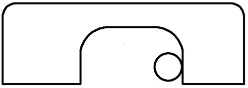
The Turkish subway frame (see Figure 1) is a Japanese-shaped structure consisting of two side beams, one beam and two end beams. The center of the left and right side beams is 1 880 mm and the side beams are 2 970 mm long. Due to the compact structure and many accessories, the positioning and clamping points of the frame during processing are difficult to find. The intermediate beam is composed of two transverse tubes, which consist of a lateral stop, a gearbox support, a motor suspension, an anti-shedding plate and a track brake. The side sill is mainly composed of an air spring guide cylinder, an air spring seat plate, a stone slab seat plate and a spring plate (inside and outside). All of the above positions require key processing and are difficult to process. The end beam structure is relatively simple, only the brake bearing, although the brake bearing hole is not processed, but because the brake bearing is very important, the X, Y, Z direction reference is determined by it.
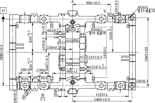
Figure 1 Turkish subway structure
2. Analysis of Difficulties in Turkish Metro Architecture
(1) The thickness of the beam body and the beam body of the entire frame of Turkey are relatively thin, and the frame is prone to deformation during the clamping.
(2) The accuracy of the hole of a spring block is φ130+0.208 +0.145mm and the depth is 37+0.5 +0mm. The precision requirement is relatively high. The bottom plane of the hole has a margin larger than 5mm to be processed, and it is a blind hole. It is not possible to directly perform rough boring, and the bottom of the hole should be rounded.
(3) There are four 60mm U-shaped groove anti-drop devices on both sides of the frame side beam. Due to the excessive allowance of the outer parts and the R10mm arc corner at the corner, the general high-speed steel tool processing efficiency is not high.
3. Choose a process plan
Through careful analysis of the overall processing pattern of the Turkish frame, it is found that both the front and the back of the frame need to be processed. The reverse side of the frame needs to be processed into a series of spring seat plates (inside and outside), track brake faces, holes in the stone block seat plate, gear box supports and The board is peeled off, and the front side of the frame only needs to process the air spring seat plate and the motor suspension seat. Our existing machine tools cannot be machined on the machine once, and the frame needs to be flanged to complete the machining. Because there are many processing parts on the reverse side of the frame, and positioning and clamping are relatively easy, it is decided to machine the reverse side of the frame first, and then the clamping frame is positioned in the plane of the processed spring plate (inner) to machine the front of the frame. This can minimize the error caused by the two clamping of the frame to meet the design requirements of the pattern.
4. Solve the difficulties in the overall processing of the Turkish subway structure
(1) The mounting of the frame. Because the Turkish frame design is relatively thin, including the side beam, the end beam body and even the entire frame, it is easy to be deformed after clamping by the pressure plate. Most of the key machining positions are distributed on the side beam body, and the machining allowance is large. The cutting resistance generated by the tool during processing is also relatively large. Therefore, after comprehensively considering the interference in the machining, we press the six compression points to press the pressure plate, and press the pressure plate on the inner side of the four 60mm anti-drop seats. , and the middle position of the two front and rear end beams (see Figure 2).
Figure 2 Frame mounting method
After the alignment of the frame is straightened, in order to prevent the press-fit deformation of the overall frame during compaction, it is critical that the position of the frame-assisted support is placed. In addition to being placed under the pressure plate, auxiliary support is also provided under the two diagonal traversing frames. After tightening the pressing points with your hands, use a pipe wrench to pre-tighten it once, and make sure that the support is tight, and then make the final clamping to ensure that the frame does not deform when clamping.
(2) Processing of a series of spring seat plate holes. During the processing of the frame, it was found that due to the deformation during welding, the hole of the spring plate was severely eccentric, and the pattern required the accuracy of a spring plate hole to be φ130+0.208 +0.145mm and the depth was 37+0.5 +0mm. (See Figure 3).
Figure 3 a spring seat plate hole
Because the aperture precision requirements are relatively high, after analysis, it is decided to use φ50mm corn milling cutter, spiral milling the bottom surface of the hole to 37+0.5 +0mm, the bottom diameter of the hole is 100mm, the rotation speed is n=300~400r/min, and the feed speed vf= 300 ~ 400mm / min; then the Z direction is raised 5mm, leaving a machining allowance for the rounding, and then rough milling a spring seat plate (inside, outside) hole to φ129.4mm, speed n = 400 ~ 500r / min Feeding speed vf=300~400mm/min; then use φ32mm R5mm rounding knife to round the hole bottom; finally use φ130mm fine boring tool to boring to φ130+0.208 +0.145mm, speed n=150~ 200r/min, feed rate vf=30mm/min. This sequence arrangement ensures that the sharp boring tool tip is not easily damaged. Only when the boring tool tip is not damaged or worn, can the dimensions of the eight spring-type spring plate (inner and outer) holes reach the pattern. Design requirements. The machining process of the air spring hole and some of the tools used in the machining are shown in Fig. 4.
(a) φ50mm corn milling cutter rough milling one spring seat plate
(b) φ130mm fine boring tool
Figure 4 Processing of a spring seat plate hole
The spiral milling process for a series of spring seat plates (inside and outside) is as follows:
Main program
O0001
G54G90G17; (establishing a plane coordinate system)
#2214=198.5; (tool length value)
#2215=50/2-0.3; (tool radius compensation value)
G43G90G00Z300H14; (establish tool length compensation)
G52X[1350/2]Y-940; (coordinate translation)
M03S500; (spindle forward rotation)
G90G0X0Y0; (quick positioning to offset coordinate origin)
G00Z-25.25; (tool fast point positioning to the subroutine Z direction starting point)
M98P0002; (call subroutine O0002)
G52X[-1350/2]Y-940; (coordinate translation)
M98P0002; (call subroutine O0002)
...
Subroutine
O0002
G54G90G17;
G01G91X25F100; (linear interpolation to spiral milling XY starting point)
#1=1;(Variable initial value)
WHILE[#1LE12]DO1; (loop judgment statement)
G91G03X0Y0Z-1I-25F450; (spiral milling)
#1=#1+1;(variable increment value)
END1; (end of cycle)
C03X0Y0I-25; (circular interpolation milling flat bottom plane)
G90G01X36F100; (linear interpolation preparation for expanding the bottom circle)
G03I-36F200;
(milling round to 122mm)
G91G01Z5; [Z-direction elevation 5mm (reserved margin for rounded corner R5mm)]
G90G01G41X[130/2]YOD15F100; (establish radius compensation)
G03I-[130/2]F400; (rough milling to 129.4mm)
G90G00G40X0Y0; (cancel radius compensation)
G52XOYO; (cancel coordinate translation)
G90G00Z200; (return to the safety plane)
M99; (the end of the subroutine call)
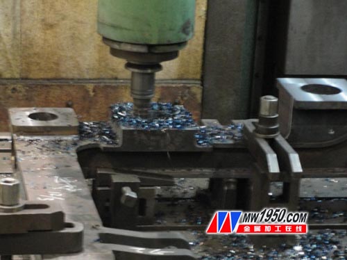
(3) Optimization of the processing technology of the 60mm U-shaped groove of the anti-drop seat. In the overall frame processing of the Turkish subway, due to the relatively large amount of welding, the machining allowance is large. When the U-shaped groove around the side beam is prevented from falling off the seat plate, if the contour milling is directly performed according to the general processing method, the machining efficiency is obtained. Very low, the tool damage is serious. Because the machining of the corner area is inevitably encountered in the machining, if the straight path is used to feed the tool at the corner, the cutting angle of the tool and the workpiece increases as the tool is machined to the corner of the arc, and the cutting arc length of the milling cutter occurs. The mutation, and the average milling force per tooth is related to the cutting arc length, so the average milling force also mutates at the corner. The load of the tool is suddenly increased, exceeding the bearing strength of the tool, and the milling cutter is frequently broken.
The main reason for the establishment of the milling cutter is that the load during corner machining increases sharply. If the machining allowance of the corner is small and the tool is machined to the corner, the load on the end mill will be greatly reduced. Then, when processing the corner of the U-shaped groove of the anti-drop seat, the most important thing is to first process the margin at the corner, and use the φ20mm drilling and milling cutter (see Figure 5) to insert the circular arc into the R10mm at the corner of the arc. size. During the drilling and milling process, the tool makes the feed motion along the axis of the spindle, and uses the cutting edge at the bottom of the tool to perform the drilling and milling combination cutting. Therefore, it is of great significance to the corner machining, and fundamentally solves the corner machining problem. The high-strength solid carbide end mill is used to carry out the linear milling of the remaining part to complete the final forming of the U-groove cavity of the anti-drop seat. The processing effect comparison is shown in Figure 6 and Figure 7.
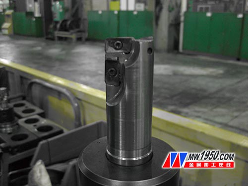
Figure 5 φ20mm drilling and milling cutter
Figure 6 Direct processing corner arc resistance increase
Figure 7 Drilling and Milling Cutter Milling Corner Arc and then Linear Milling
5 Conclusion
Through the process analysis of the Turkish Metro train structure, through a series of improvement measures, as well as clear anatomy in some difficult machining locations, determine the appropriate route, and adopt the appropriate processing scheme to ensure the efficiency of Turkish subway frame processing. With quality. Turkey's air spring hole processing method provides a good reference for the subsequent Ankara framework and the Anbang line structure, laying a solid foundation for these similar large blind hole processing. The processing of the inner cavity corner and the rational use of the end mill greatly improve the production efficiency.
references:
[1] Yang Liming. Machine Tool Fixture Design Manual [M]. Beijing: National Defence Industry Press, 1996.
[2] Liu Wenjian. Handbook of Fixture Engineer [M]. Harbin: Heilongjiang Science and Technology Press, 1992.
[3] Zhou Zehua. Principles of Metal Cutting [M]. Shanghai: Shanghai Science and Technology Press, 1993.
4 Wire Video Door Phone is designed for villa or single family residences and small apartments.4-wire connection with good system compatibility. Support more outdoor units connected at the same time.The indoor units can be used for individual house door phone as well,direct call to each user from outdoor unit.Outdoor unit direct push button up to 12 buttons.
1. Wired door phone Functions
1 Indoor unit audio&video intercom, monitor, unlock.
2 infrared night vision, metal camera. rainproof cover
3 7 inch TFT color display screen, clear vision and voice
4 1pcs camera can support 4 pcs monitors
5 Wired operation, very easy to install.
6 Good security product for modern family
2. Specifications
Outdoor camera
Power DC14V (Receive power from monitor )
Camera 1/3CCD or 1/4CMOS
Illumination 6 pcs Infrared light
size 115 × 115 × 40mm
Indoor monitor
Power Input:AC100-240V 50/60HZ
Output:DC 14V/1.2A
Screen 7" TFT LCD:800*480
Communication Model Hand free Communication
4-wire Connection
Chime Melody16Chimes
Maximum Power Consumption 16.8W
Dimensions 230×150 × 32mm
3. Packing
1set/gift box
12sets/carton


Wire Video Door Phone
Wireless Doorbell Video Door Phone,Wireless Doorbell Camera Intercom,Wireless Colour Video Door Phone,Wireless Wifi Video Door Phone
Shenzhen Zhuohao Intelligent Electronic Development Co., Ltd. , https://www.szactop-smart.com