Today, the development of low-power electronics technology allows battery-powered sensors and other devices to be located far from the grid. In an ideal situation, in order to truly get rid of the shackles of the grid, the need to replace batteries should be eliminated, and instead the batteries should be recharged with renewable energy (such as solar energy) provided by the local environment. This design note explains how to build a compact battery charger that operates on a small dual-cell solar panel. The uniqueness of this design is that the DC/DC converter uses power point control to draw the maximum power from the solar panel.
The importance of maximum power point control
Although solar cells or solar panels are categorized according to power output, the available power of the panels is rarely constant. Its output power depends to a large extent on lighting, temperature, and load current drawn from the panel. To illustrate this, Figure 1 shows the VI characteristic of a dual-cell solar panel under constant light conditions. The IV curve has relatively constant current characteristics in the short circuit (leftmost) to approximately 550 mA load current, followed by constant voltage characteristics at lower current conditions, and tends to be open (rightmost) at open circuit conditions. Near the maximum voltage. The power output curve of the panel shows that the power output shows a significant peak at about 750mV/530mA (the inflection point of the IV curve). If the load current increases beyond the power peak, the power curve rapidly drops to zero (leftmost). Similarly, light loads also tend to power to zero (far right), but this is often less of a problem.
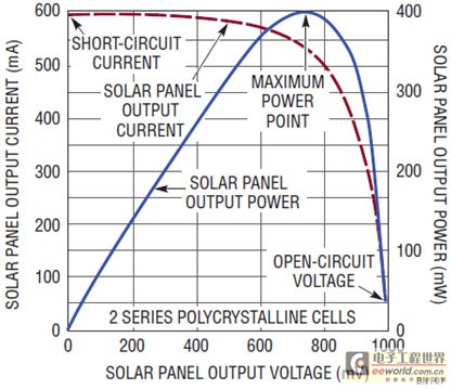
Figure 1: Output voltage, current, and power of a solar panel.
Of course, the lighting conditions of the panel will affect the available power - the light output will be lower if the lighting is low, and the power output will be higher if the lighting is more. Although illumination directly affects the size of the peak power output, it does not have a large effect on the position of the peak on the voltage scale. That is, the panel output voltage with peak power remains relatively constant regardless of lighting. Therefore, it is advisable to moderate the output current so that the solar panel voltage is at or above this peak power voltage (here 750mV). This practice is called Maximum Power Point Control (MPPC).
Figure 2 shows the effect of changes in sunlight on the charging current with and without maximum power point control. The simulated sunlight intensity dropped from 100% to about 20% and then back to 100%. Please note that when the sunlight intensity drops to around 20%, the solar panel's output voltage and current also drop, but the LTC®3105's maximum power point control prevents the solar panel's output voltage from dropping below the 750mV setting. It does this by reducing the output charging current of the LTC3105 to prevent the solar panel voltage from dropping abruptly to near 0V, as shown in the plot to the right in Figure 2. In the absence of power point control, a small drop in the intensity of sunlight completely blocks the flow of charging current.
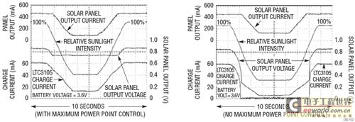
Figure 2: Changing the intensity of sunlight can affect the charging current.
LTC3105 Boost Converter with Input Power Control
The LTC3105 is a synchronous step-up DC/DC converter designed to convert the power from environmental energy sources such as low-voltage solar cells and thermoelectric generators into battery charging power. The LTC3105 uses MPPC to deliver the maximum available power from the energy source. It does this by reducing the output current of the LTC3105 to prevent the solar panel voltage from dropping abruptly to nearly 0V. The LTC3105 can start up with an input voltage as low as 250mV, allowing it to be powered by a single solar cell or up to 9 or 10 cells connected in series.
The output disconnect feature eliminates the isolation diodes often required for other solar powered DC/DC converters and allows the output voltage to be higher or lower than the input voltage. The 400mA switch current limit is reduced during start-up to operate with a relatively high-impedance power supply, but still provides adequate power for many low-power solar applications once the converter is in normal operation. In addition, the LTC3105 features a 6mA adjustable output low dropout linear regulator, open-drain power-good output, shutdown inputs, and Burst Mode® operation to improve efficiency in low-power applications.
Solar-powered lithium-ion battery charger
Figure 3 shows a compact solar-powered battery charger that uses the LTC3105 as a boost converter and the LTC4071 as a parallel charger for Li-Ion batteries. A dual-battery 400mW solar panel is responsible for supplying input power to the LTC3105 to generate more than 60mA of charge current in sunny conditions. As shown in Figure 1, the maximum power point control prevents the solar panel voltage from dropping below the 750mV maximum power point. The converter's output voltage is set to 4.35V, slightly higher than the 4.2V floating voltage of Li-Ion batteries.
The LTC4071 shunt charger limits the voltage across the battery to 4.2V. Grounding the FBLDO pin sets the low-dropout regulator to 2.2V and is used to power the "charge" LED. This LED turns on when the battery is charging, and turns off when the battery voltage is within 40mV of the float voltage (indicating that the battery is near full charge). An NTC thermistor is used to sense the battery temperature and lower the LTC4701's float voltage at high ambient temperatures to improve battery safety. To protect the battery from damage caused by over-discharge, the low battery disconnect feature disconnects the battery from the load when the battery voltage drops below 2.7V.
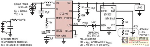
Figure 3: Dual-Battery Solar Panel and Li-Ion Battery Charger.
in conclusion
Although the circuit described herein can generate only a few hundred mW of power, it can provide enough power to maintain a 400mAhr Li-Ion battery fully charged under most weather conditions. The combination of low input voltage and input power control makes the LTC3105 ideal for low power solar applications. In addition, the LTC4071 parallel charging system complements the LTC3105 by providing precise floating voltage, state-of-charge, and temperature-safety features to ensure long-term battery life in outdoor environments.
Precision Chucks,Chuck Surface,Chuck Material
Keyli Magnetic Material Co., Ltd. , http://www.cxmagnet.com