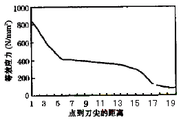
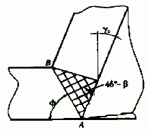
Modern metal cutting technology is developing in the direction of high speed, high efficiency, high precision, low cost, resource conservation, and environmental protection. The traditional tool development process needs to go through many stages such as material development → tool design → manufacturing molding → cutting test → feedback modification → input into production, and the development cycle is very long, which has been difficult to meet the requirements of modern cutting technology development. In recent years, there has been a new technology based on modern mathematics, mechanics and other multidisciplinary theories, with the help of computer technology and advanced algorithms - virtual design technology. This technology can be used to numerically simulate many engineering problems, which can speed up product design and improve design accuracy and reliability.
Virtual design technology can also be applied to the research and development of metal cutting tools. By inputting material performance parameters into the computer, establishing finite element model, loading, calculation and other steps, the whole cutting process can be simulated realistically and the tool geometry parameters can be optimized. The application of this technology can not only greatly shorten the design and development cycle of tool products, but also improve the success rate and reliability of the design.Numerical simulation technology is the core technology of virtual design, and the main analysis method adopted by numerical simulation technology is finite element method. In recent years, finite element analysis technology has been continuously developed under the impetus of the development of computer technology, and many excellent finite element analysis softwares have been developed, which has greatly promoted the promotion and application of virtual design technology.
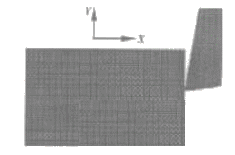
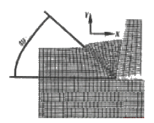
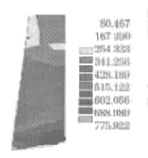
This study applied the international large-scale finite element software ANSYS, successfully simulated the change of the stress of the tool during the metal cutting process and the formation process of the shear angle, and carried out a series of calculations with the tool front angle as the variable to verify the tool. The relationship between the rake angle and the shear angle. In the cutting process, many factors affecting the above-mentioned change process are not only determined by the tool geometry parameters, the amount of cutting, etc., but also closely related to the material properties of the workpiece. In the numerical simulation process, not only material nonlinearity, geometric nonlinearity and state nonlinearity are considered, but also the choice of the solver and the control of the load step are also strictly required. The powerful nonlinear processing capabilities of ANSYS software provide powerful assistance for numerical simulation of cutting processes. 1 Modeling and calculationFinite element modeling Establishing the correct finite element model is the key to achieving numerical simulation. In combination with the actual situation of metal cutting, the following issues should be considered in modeling:
|
| (1) |
Where: e pl - plastic strain of the materialL——plastic increment coefficient
Q - the stress function that determines the strain direction of the material
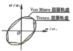
With the development of plastic strain, the yield criterion can be described by two kinds of strengthening criteria: isotropic strengthening and follow-up strengthening. In this study, the multi-linear isotropic strengthening criterion (MISO) is adopted, which uses input of up to 5 stress-strain data points. The method is used to represent the stress-strain curve and is suitable for compliance with Von Mises yield criteria, proportional loading, and large strain analysis.
During the chip formation process, the change of the unit displacement and the change of the unit orientation in the chip affect the overall stiffness of the model. This is a geometric nonlinear problem including large strain and large deflection. For such problems, the large strain effect can be activated. The equation iterates out a correct solution. There is friction between the tool rake face and the chip and between the tool flank and the machined surface. In order to correctly describe the friction model, the state nonlinear contact problem of the whole process must be considered. In this study, the contact mode of the rigid body to the flexible body is selected. Since there are bonding areas and sliding areas on the rake face, and the positions of the two areas vary depending on the cutting conditions, it can be controlled by setting a maximum allowable shear stress t max , that is, an area where the interface shear stress is lower than t max For the bonding area, the area where the interface shear stress is higher than t max is the sliding area. In order to make the numerical simulation experiment more representative, the cemented carbide WC-TiC-TaC-Co was selected as the tool material, and its elastic modulus E=550GPa, Poisson's ratio μ=0. 3; A3 steel was selected as the workpiece material. , the elastic modulus E = 210 GPa, Poisson's ratio μ = 0.3, the ultimate stress s b = 520 MPa, the yield stress s s = 320 MPa, and the ultimate deformation is 20%.
| ||||||||||||||
| ||||||||||||||
| ||||||||||||||
| ||||||||||||||
| ||||||||||||||
|
Next page
Galvanized Steel Sheet,Galvanized Plain Sheet,Stainless Steel Sheet,Carbon Steel Sheet
Zhongyan Machinery Co., Ltd. , http://www.juhengflanges.com
