4. Use of the center frame and the tool holder
When the ratio of the length of the workpiece to the diameter is more than 25 times (L/d>25), the rigidity of the workpiece itself deteriorates. When turning, the workpiece is subjected to bending force and vibration due to the cutting force, self-weight and centrifugal force during rotation. Seriously affects its cylindricity and surface roughness. At the same time, during the cutting process, the workpiece undergoes bending deformation due to thermal elongation, turning is difficult to carry out, and in serious cases, the workpiece is caught between the top ends. At this point, the center frame or the tool holder is required to support the workpiece.
1) Support the slender shaft of the car with the center frame
Generally, when the slender shaft is turned, the center frame is used to increase the rigidity of the workpiece. When the workpiece can be segmented, the center frame is supported in the middle of the workpiece, as shown in FIG. Before the workpiece is mounted on the center frame, a groove supporting the support claw of the center frame must be pulled out in the middle of the blank, the surface roughness and the cylindrical error are small, and lubricating oil is often added at the contact between the supporting claw and the workpiece. In order to improve the accuracy of the workpiece, the axis of the workpiece should be adjusted to be coaxial with the center of rotation of the machine tool spindle before turning.
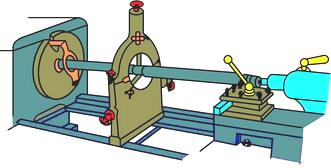
Figure 5: Supporting the slender shaft with a center frame
When the groove of the support center frame is difficult or some of the slender shafts that do not need to be machined in the middle section, the transition sleeve can be used to make the support claws contact the outer surface of the transition sleeve, as shown in Fig. 6, the two of the transition sleeves. The ends are each provided with four screws, which are used to clamp the surface of the blank and adjust the axis of the outer circle of the sleeve to coincide with the axis of rotation of the spindle.
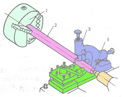
c) use with the knife holder
1. Three-jaw chuck 2. Workpiece 3. Knife holder 4. Top tip
Figure 6 Supporting the long axis with the tool holder
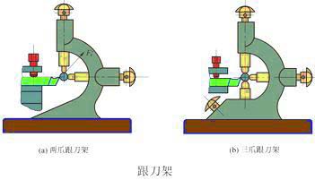
2) Support the slender shaft of the car with the turret
For slender shafts that are not suitable for turning head turning, they cannot be supported by the center frame, but are turned with the tool holder support to increase the rigidity of the workpiece, as shown in Fig. 6. The tool holder is fixed on the saddle. Generally, there are two supporting claws, which can follow the movement of the turning tool to offset the radial cutting force, improve the shape accuracy of the turning elongated shaft and reduce the surface roughness, as shown in Fig. 6a. Two-jaw and tool holder, because the cutting resistance F ' r of the turning tool to the workpiece, the workpiece is attached to the two supporting claws of the tool holder, but due to the downward gravity of the workpiece itself and the occasional bending, the turning will be instantaneous Vibration occurs when leaving the support claws and contacting the support claws. Therefore, the ideal center frame requires a three-jaw center frame, as shown in Figure 6b. At this time, the three claws and the turning tool are pressed against the workpiece so that the upper and lower sides and the left and right sides cannot move, and the turning is stable, and vibration is less likely to occur.
5. Mount the workpiece with a faceplate, a seesaw and a pressure plate and bolts.
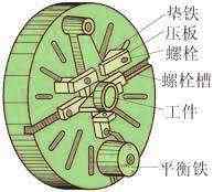
Figure 7 Installing the parts on the faceplate
Irregularly shaped workpieces, workpieces that cannot be clamped with three- or four-jaw chucks can be clamped with a faceplate. The face plate is a large disc mounted on the spindle of the lathe. Many long grooves on the surface of the plate are used to put the bolts. The workpiece can be directly mounted on the faceplate by bolts, as shown in Fig. 7. It is also possible to firmly hold the auxiliary supporting angle iron (bending plate) on the faceplate with screws, and the workpiece is mounted on the curved plate. Figure 8 shows the case where the end face and the inner hole of a bearing housing are clamped on the faceplate. In order to prevent vibration when the center of gravity is deflected while rotating, balance iron is added to the other side of the workpiece. The position of the workpiece on the faceplate needs to be carefully corrected.
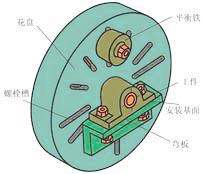
Figure 8 Installing parts with curved plates on the faceplate
Previous page
Plastic Blow Molding Machin,Plastic Bucket Blowing Machine,Water Tank Blowing Machine
Futian Machinery Co., Ltd. , http://www.skywin-extruder.com